Introduction
X400 is a programmable gateway that automatically connects to Microsoft Azure. It’s provided with MyMote: a web-based management dashboard for provisioning, device software update and other common IoT administration tasks.
X400 sends two different types of messages to the cloud:
- Data: messages coming from the Arduino-App running on X400 such as sensors’ readings, machines status and many others. Each message is forwarded to your queue on the Microsoft Azure Service Bus and it is available to any application (a web app, a function …). Each X400 gateway has a maximum of 100 messages per day (message size 3,75Kb)
- Management: messages exchanged with the cloud for admin operations (such as OTA device software update and others). Notifications are special messages coming from the device and visualized directly on MyMote web dashboard.
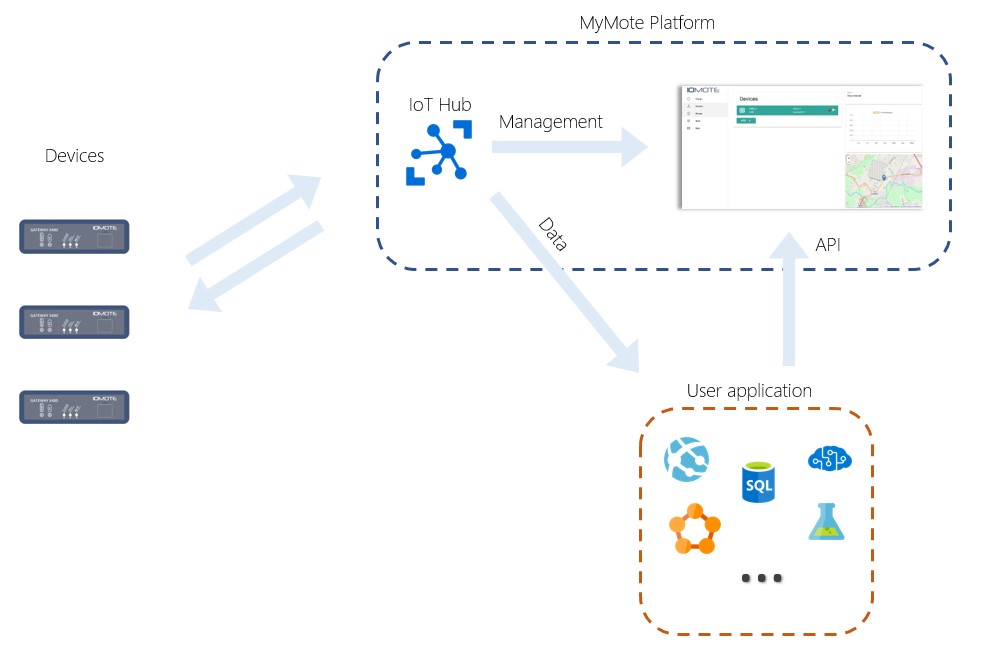 MyMote platform architecture
MyMote can be accessed via browser on any device with username and password authentication. A set of REST-API are available to get information on each device or to automate device-level operations (OTA and others). In the next chapters you will learn how to use MyMote platform and how to create App running on X400 gateway.
Device Management
In the Devices section is possible to add a new device to your account (Provisioning) and to manage the existing ones. Each device has the following properties:
- Name: a friendly name set during provisioning (Note: it can’t be changed later!)
- Type: model of the device, for ex. X400.
- OS: The version of the Iomote communication framework.
- App: Name and version of the your App
- Location: device position on the map
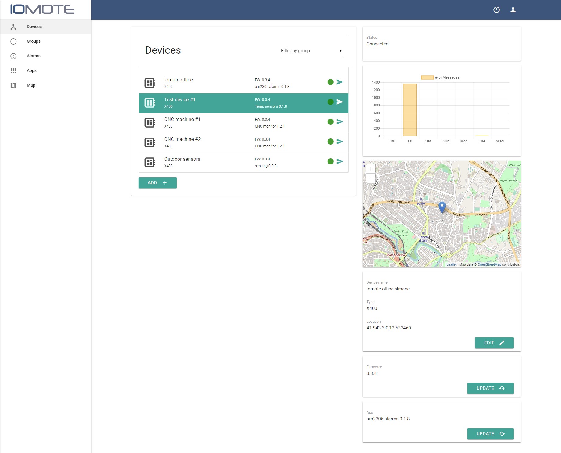 Devices section
Provisioning
Add a new Device to your account
Click on ADD + button to start the provisioning of a new device. On the form you are asked to insert:
- Device Key: it’s the unique ID of the device (64 chars).
- Name: Friendly name.
- Location: Manual entry the gps position (Lat,Lon)
- Group: assign the device to a specific group
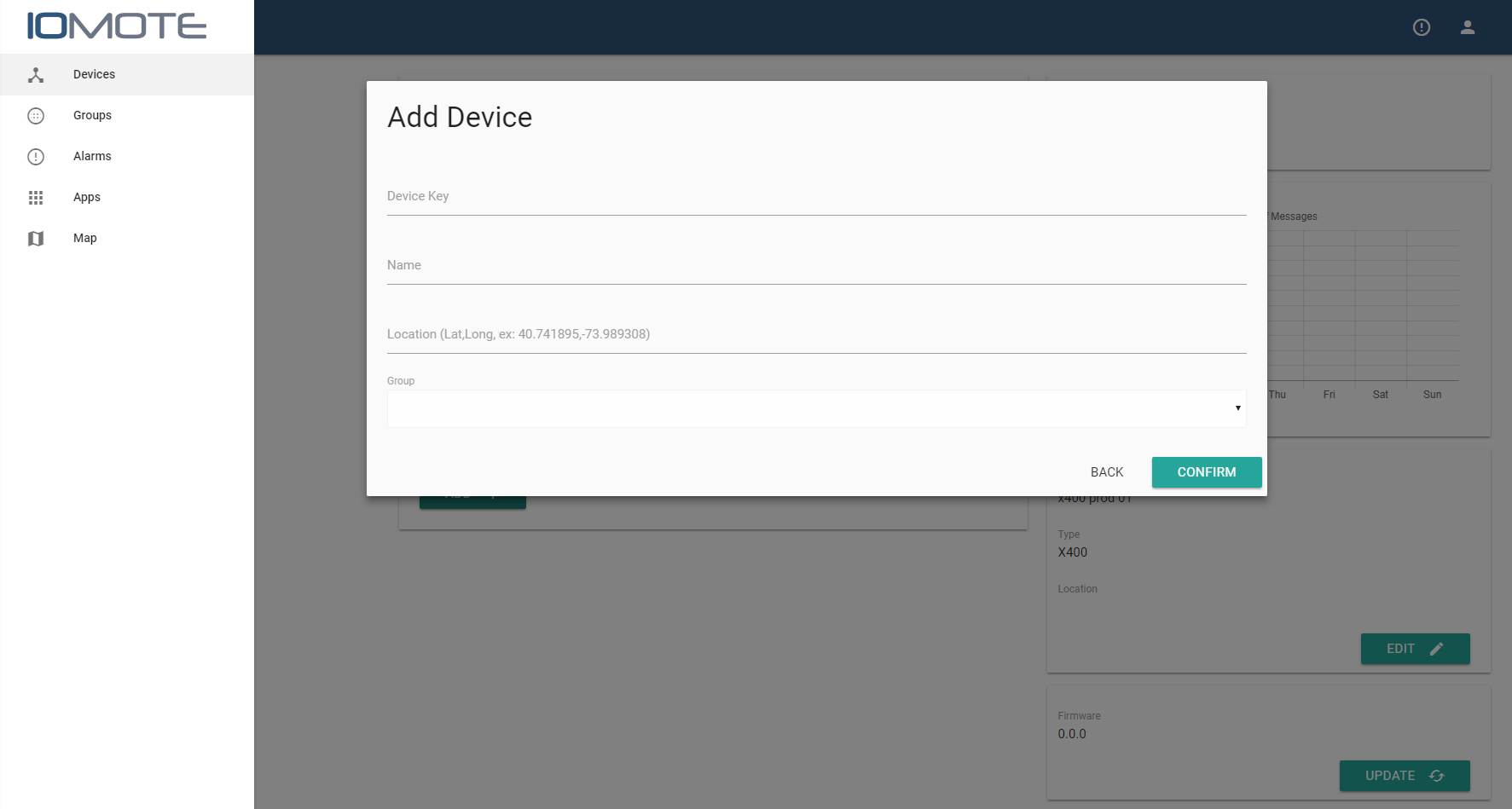 Adding a new device
Things to keep in mind before adding a new device:
- Internet connection: for the first installation the device must be connected via Lan Cable (even for the 2G/3G versions) to a DHCP enabled router.
- Computer and USB cable: to read the device key connect the device to a PC via USB. Open a serial monitor software (115.200 baud/8/N/1) and at after the boot the device will write its device key.
- SIM activation: X400 models provided with 2G/3G connectivity are provided with a SIM card. Please note that the activation of the SIM may take up to 2 hours (only the first time).
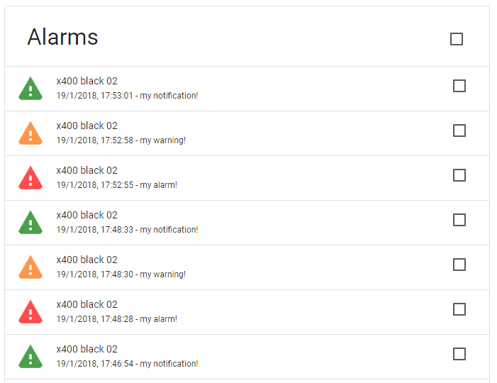
Notifications
In this section you can see the received notifications from the devices. Notification are classified under three categories:
- Info: green icon
- Warning: yellow icon
- Alarm: red icon
App Management
Upload and manage your Apps and versioning directly on the cloud.
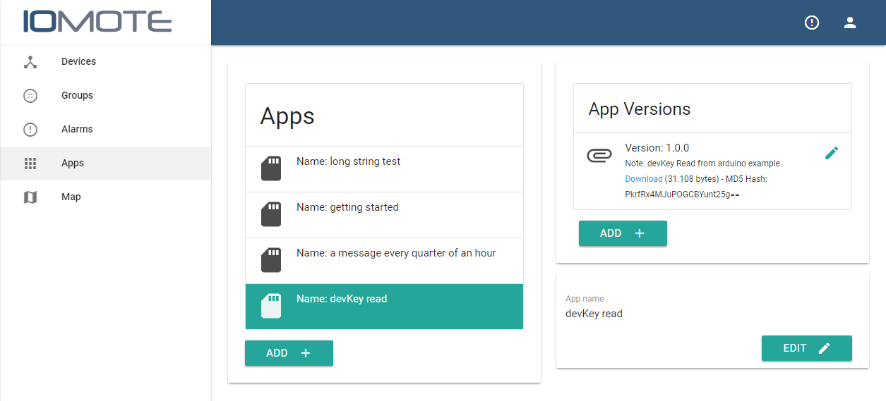 Adding a new App or a new version of an existing App is easy just click on ADD + button
Note: apps must be in .bin format compiled for the App-processor using the Arduino IDE or an equivalent tool.
Where is my .bin file?
If you use the Arduino IDE go to menu Sketch -> Export compiled sketch. The .bin file will be created and saved in the project folder.
If you use the Visual Studio Code open the file arduino.json that is inside the .vscode folder of your project and insert the string “output”: “./build”. The bin file will be saved inside the /build folder.
Before starting
Before starting you have to execute some steps to get your system ready to work with X400 and MyMote platform.
- Get an account on MyMote platform (it will be provided with your first X400 dev kit purchase).
- Install the Arduino IDE on your computer. (you can download it form www.arduino.cc Windows - Linux - Mac)
WARNING: (for Windows users) download the installer from arduino website, not the app from the Windows store (we had problem with that version of the IDE).
- Once the Arduino IDE is installed you have to add the X400 libraries:
- Go to menu File -> Preferences
- On the Additional board manager URLs, add: https://github.com/iomote/arduino-ide-bsp/raw/master/package_iomote_index.json (use comma if there are other addresses) and confirm.
- Open the Board manager (menu Tools -> Board:xxx -> Board Manager)
- Search and install the package Arduino SAMD Boards (32.bits ARM Cortex-M0+) by Arduino
- Search and install the package Iomote X400 by Iomote
- Open the Library Manager (menu Sketch -> Include Library -> Manage libraries)
- Install the library RTCZero by Arduino
- Select X400 from Tools -> Board:xxx -> Iomote X400
- Now the IDE is ready to create App for X400.
Device provisioning
IMPORTANT:
For the first installation of a new X400 device (even for cellular versions) you need an Internet connection via ethernet (with a DHCP enabled router).
At startup X400 connects automatically to the cloud, waiting to be paired with a specific account.
Login using your username and password on cloud.iomote.com and go to Devices page and click on “ADD +” button. You will be required to insert name and Device Key of your gateway, location and group are optional. Since it is probably your first device, Groups may not be available yet on your account. Don’t worry: you can create groups and assign devices to any created groups later.
How to get the Device Key?
The factory app pre-loaded on X400, writes on the USB-serial port the Device Key. To read it:
- connect the front USB to your computer
- use a serial monitor tool (Arduino IDE has its one), with the settings 115200 8/N/1.
- push the front button P1 and the device will write the Device Key on the serial port, copy and paste it on the MyMote portal
If you have overwritten the default app and you need the device key, don’t worry, you can find the code of the app in the Iomote GitHub account or just use the proper command in you app to read the Device Key (have a look a the initialization section)
When the form is filled, the device is reset. The operation will be confirmed by the front CLOUD LED colors (you can refer here). Just wait for the LED to become firmly GREEN.
Once the pairing procedure is complete, your device communicates with your MyMote cloud (it takes up to five minutes to see your device online, even if it’s already up and running, and you can already send data to the cloud). In the meantime the SIM card of the device is activated (if your device has 2G/3G features), the activation process may take up to two hours.
Your first X400 app
sending data to the cloud
Let’s code your first Arduino App to send data from the device to the cloud. First connect your X400 to your computer via USB, then open the Arduino IDE and set the right virtual COM port (menu Tools -> Port). Create a new Sketch a copy/paste the code:
- if you don’t have a starter kit, go to the GitHub page for the getting started app
- if you have a starter kit go to the GitHub page for the starter kit app to get an app sending real data Then, in the menu, select Sketch -> Verify/Compile. Now your App is compiled and ready to be uploaded to your X400 device: Sketch -> Upload and wait for the device to be ready.
App usage
open the serial monitor inside the Arduino IDE (Tools->Serial monitor) and select the proper COM port, so you’ll get debug messages.
Push the front button to send messages to the cloud.
Reading the messages from the cloud
Once the app is up and running on the device, you can read the incoming data accessing directly the service bus. Microsoft has released libraries in several programming languages, on the Iomote Git Hub account you can find example for NodeJS and C# (.NET Core). Both applications are very basic example of usage, reading the data from the service bus and writing it back on the terminal. They can be used as starting point for your application, to redirect data to your azure services or to store it inside your database.
Intro
X400 is composed by two parts:
- Iomote Core: running Iomote OS, manages the communication with the cloud (Ethernet, celllular…), the security and the off-line messages storage. It solely serves as “cloud postman” for the App-processor.
- App-processor: Arduino-compatible, available to run your specific application such as a reading a sensor or interfacing a serial device. It is directly wired with the connectors of the gateway.
These two parts communicate with easy-to-use serial API, so the App-processor can easily send data to the cloud, without.
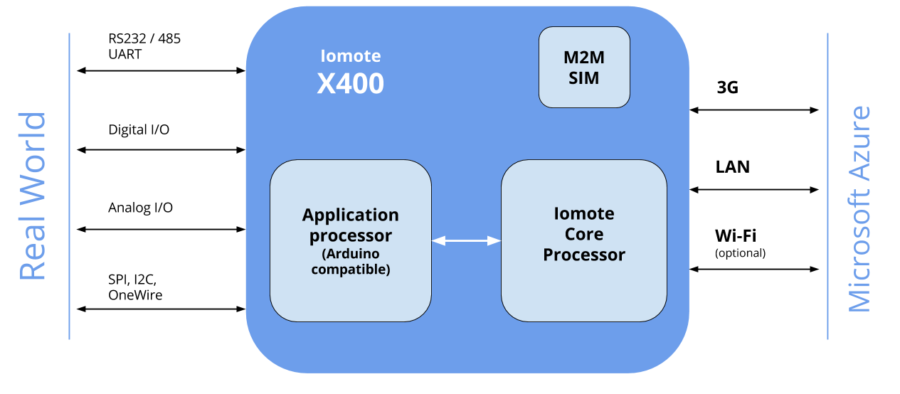 X400 System Architecture
X400 offers several connectors with I/O, serial port and other signals managed by the App-processor.
- Front panel: status leds and pushbuttons
- Main connector: screw connectors on both sides of X400
- Expansion connector: TTL level signals (3.3V)
Front panel
The front panel of the X400 contains:
- Button “RESET”: resets only the app-processor (not the Iomote Core) and restarts the app.
- Button “P1”: button available for the user application
- LED “CLOUD”: shows the status of the cloud connection
- LED “STATUS”: Led available for the user application
- micro USB port: serial port to communicate with the app-processor, can be used to download the app on the device and for debug purposes.
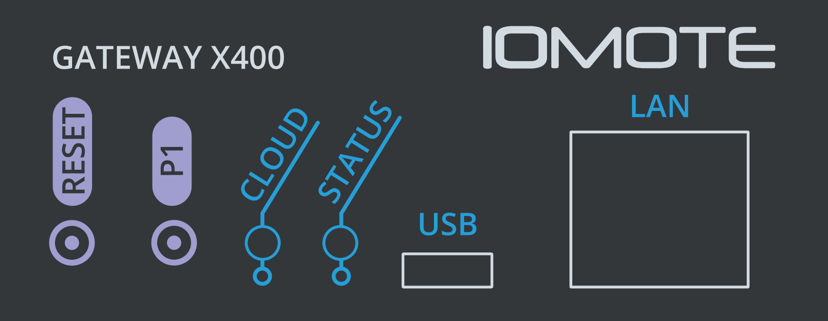 X400 Front Panel
The front leds show the status of the device in several conditions reported in the table:
| CLOUD | STATUS | DESCRIPTION |
|---|---|---|
| - | GREEN fast blink | App-processor restarting |
| RED fixed | - | Hardware fault (device will be reset in 1 min) |
| RED blinking | - | Network - Error |
| ORANGE blinking | - | Network - Connecting |
| ORANGE fixed | - | Network - Disconnected (device automatically will try to reconnect in few seconds) |
| GREEN blinking | - | Cloud - Connecting |
| GREEN fixed | - | Cloud - Connected |
| GREEN/ORANGE blinking | - | FOTA OS/App |
Main connector
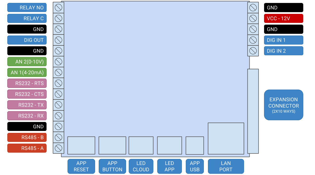 Overview of the gateway (top-view) and signals on main connector
Main connector pinout:
| PIN | NAME | DESCRIPTION |
|---|---|---|
| 1 | GND | Ground Input |
| 2 | VCC | Power supply input (9-24V 2A) |
| 3 | GND | Ground Input |
| 4 | DIG IN 1 | Digital input (Dry input) |
| 5 | DIG IN 2 | Digital input (Dry input) |
| 6 | RELAY NO | Relay normally open contact |
| 7 | RELAY C | Relay common contact |
| 8 | GND | Ground |
| 9 | DIG OUT | Digital output (open collector) |
| 10 | GND | Ground |
| 11 | AN 2 | Analog input 0-10V (12bit ADC) |
| 12 | AN 1 | Analog input 4-20mA (12bit ADC) |
| 13 | RS232-RTS | Serial port RS232 RTS (Output) |
| 14 | RS232-CTS | Serial port RS232 CTS (Input) |
| 15 | RS232-TX | Serial port RS232 TX (Output) |
| 16 | RS232-RX | Serial port RS232 RX (Input) |
| 17 | GND | Ground |
| 18 | RS485-B | Serial port RS485 (signal B) |
| 19 | RS485-A | Serial port RS485 (signal A) |
Expansion connector
The expansion connector uses 3.3V level signals and is generally used for prototyping or to connect expansions, like the dev kit with sensors and display.
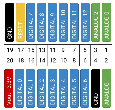
Expansion connector pinout:
| PIN | NAME | DESCRIPTION |
|---|---|---|
| 1 | A0 | Analog input 0-3.3V (12bit ADC) |
| 2 | A1 | Analog input 0-3.3V (12bit ADC) |
| 3 | A2 | Analog input 0-3.3V (12bit ADC) |
| 4 | GND | Ground |
| 5 | D12 | Digital I/O |
| 6 | D6 | Digital I/O |
| 7 | D11 | Digital I/O |
| 8 | D5 | Digital I/O |
| 9 | D10 | SPI MISO signal |
| 10 | D4 | Front panel switch input (digital level: 1-open 0-pressed) |
| 11 | D9 | SPI MOSI signal |
| 12 | D3 | I2C Clock signal (should be used as i2c only!) |
| 13 | D8 | SPI Clock signal |
| 14 | D2 | I2C Data signal (should be used as i2c only!) |
| 15 | D7 | LED - Front panel led output (1-ON 0-OFF) |
| 16 | D1 | Serial1 RX (input) |
| 17 | RESET | Reset (resets only Application processor!) |
| 18 | D0 | Serial1 TX (output) |
| 19 | GND | Ground |
| 20 | 3V3 | Output (limited to max 500mA) |
Intro
Iomote library for Arduino IDE
X400 supports standard Arduino commands (for ex. digitalWrite) and specific commands available on the Iomote X400 library.
The Iomote library allows pin-level operations (for ex. Iomote.AnalogRead) and it allows to send data messages and notifications to the Cloud.
In the next chapters you will learn each specific command available on the Iomote library.
Initialization
Iomote object initialization
Most of the following commands leverages on the object Iomote, that is instantiated during the initialization phase. In the setup function it must be initialized using the proper command:
void Iomote.begin(const char *appname, uint8_t vers0, uint8_t vers1, uint8_t vers2)
Parameters
- appname: the buffer containing the name of the app (max length 100 chars).
- vers0, vers1, vers2: main, middle and lower version number for the app. (values: 0-255 for each number)
Returns
- None
The method initializes the hardware and communicates the Application name and version to the Iomote Core processor. Those parameters are sent to the Cloud only when changed, keep in mind each device has a max number of messages available per day.
NOTE: in order to avoid confusion we suggest to keep the same name for your Apps on MyMote dashboard
WARNING: the Iomote.begin method is mandatory for the app to work properly. NEVER remove it from your code!
The App name and App version running on a specific device are shown on MyMote - Devices section.
Reading the Device Key
int8_t Iomote.devKey(char* buffer)
Parameters
- buffer: the char buffer where the device key will be stored.
Returns
- 0 in case of success
- error code (refer to error codes table)
With this method it’s possible to read the Device Key. The key is long 64 chars and it’s returned as terminated array char, so the buffer must be at least 65 chars.
Syncing the real time clock
time_t Iomote.rtcSync()
Parameters
- None
Returns
- a time_t variable containing the updated date/time.
The internal RTC of the application processor is update at the device startup, but sometimes it may happens (especially with no internet connection) that the date/time is not updated so, at runtime, it’s possible to force an update with this command.
Front panel
User Button (P1)
int Iomote.buttonRead( )
Parameters
- None
Returns
- 0 (or LOW) if button is pressed
- HIGH otherwise
User LED (Status)
User LED can be driven using the default Arduino reference APIs. User LED is pin 7, its state can be changed using the standard Arduino functions digitalWrite( ... ) or analogWrite( ... )
Main connector
In this section will be covered all the commands to control the signals of the main connector. The commands are issued as methods of the object Iomote
Analog and digital IO
float Iomote.analogRead(int channel)
Parameters
- channel: the analog channel you want to read. Main connector has two analog channels:
- AN_1 can be used to read channel 1, a 4-20mA input
- AN_2 can be used to read channel 2, a 0-10V.
Returns
- A float (floating point) number with the read value, in case of channel 1 the value is expressed in mA, in case of channel 2 is expressed in Volts
int Iomote.digitalRead(int input)
Parameters
- input: the digital input number you want to read. Main connector has two digital inputs, both can be used with 0 - 24V.
- DIG_IN1 can be used to read digital in 1
- DIG_IN2 can be used to read digital in 2
- BUTTON can be used to read front panel button Returns A int number with the read value (LOW or HIGH)
void Iomote.digitalWrite(int pin, int value)
Parameters
- input: the digital output number you want to write. Main connector has two digital outputs:
- OC_OUT is an open collector output
- RELAY_OUT is the on-board relay
- value: the value you want to write (LOW or HIGH)
RS232/RS485 port
Serial port of main connector can be used as RS232 or RS485, but not at the same time. All the methods of Arduino Serial class are wrapped to Iomote class methods with similar implementations.
void Iomote.serialBegin(int baudrate, uint8_t RS485_Mode)
Parameters
- baudrate: the Serial port baudrate to be used.
- RS485_Mode:
- RTS_CTS_OFF can be used to set RS232 mode without RTC/CTS signals
- RTS_CTS_ON can be used to set RS232 mode with RTC/CTS signals
- RS485 can be used to set RS485 mode
All the other Serial class methods can be used in the same way as Arduino Reference. Following is a table with all the available methods and their equivalent for RS232/RS485 port.
| Arduino Reference | Iomote class equivalent | |
|---|---|---|
Serial.end( ) |
→ | Iomote.serialEnd( ) |
Serial.available( ) |
→ | Iomote.serialAvailable( ) |
Serial.read( ) |
→ | Iomote.serialRead( ) |
Serial.peek( ) |
→ | Iomote.serialPeek( ) |
Serial.flush( ) |
→ | Iomote.serialFlush( ) |
Serial.write( ... ) |
→ | Iomote.serialWrite( ... ) |
Expansion connector
All the signals on Expansion connector can be used as any other Arduino signals. The only limitation is on I2C SDA and SCL signals, which should always be used as I2C Bus signals, since X400 App processor provides an onboard EEPROM. This non volatile memory can be used by App processor code, using any Arduino-compatible library.
The EEPROM model is a 24AA64, it’s address is A0.
Cloud communication
X400 can be considered an “always on” device, permanently connected with the cloud. The Iomote Core manages the connection with the cloud and the messages. All the messages (data and notification) are sent from the application processor to the Iomote Core, that is responsible of storing it inside the non-volatile memory and delivering it to the cloud. If there is some issue with the connection is not a problem, because all the messages are stored inside the non volatile memory. So, as soon as the application processor sends them to the Iomote Core, they are permanently stored until they are correctly delivered to the cloud. No matter if the network goes down, no matter if the power cable is unplugged, messages are stored inside the flash memory, so, when an internet connection will be available (ethernet or 2G/3G), the device will send each pending message in memory.
In addition, X400 Iomote Core can receive user messages from cloud (cloud to device messages). Up to 10 messages can be stored on non-volatile memory, so App processor can read them without worry about timings.
Pending messages
Pending messages affect ONLY the quota of the day in which they are stored in memory.
Example: if a message is stored in memory today, but the network in not available and it’s sent the day after, the quota for the day after is still 100 messages, PLUS the pending message of the day before. This is because the message is considered “sent” in the moment it passes from application processor to the Iomote Core, no matter when it is received by the cloud.
Data Messages
int8_t Iomote.sendMessage(char* payload)
Parameters
- payload: the message to be sent to cloud. Payload max length is 3750 bytes
Returns
- 0 in case of success
- error code otherwise (refer to error codes table)
Notifications
int8_t Iomote.sendNotification(int level, char* payload)
Parameters
- level: the type of notification you want to send
- IOMOTE_NOTIFICATION used for info messages
- IOMOTE_WARNING used for warning messages
- IOMOTE_ALARM used for alarm messages
- payload: the message to be sent to cloud. Payload max length is 100 bytes
Returns
- 0 in case of success
- error code otherwise (refer to error codes table)
Pending messages counter
To get the counter of the currently queued messages, but not sent yet to the cloud by the Iomote Core processor:
int8_t Iomote.messagesPending(int16_t* pend)
Parameters
- pend: the pointer to your int16_t variable to store data read from Iomote Core (ex: use iomoteClass.messagesPending(&myVariable); on your code)
Returns
- 0 in case of success
- error code otherwise (refer to error codes table)
Check if Cloud to device User Messages are available
bool Iomote.userMessageAvailable()
Checks if there are any user messages on Iomote Core waiting to be sent to App processor.
Returns
- true in case of messages pending present on non-volatile memory
- false if no messages are present on non-volatile memory
Read User Messages content
int8_t Iomote.userMessageRead(char* buffer)
Copies the oldest user message content to provided buffer. When App processor uses such command, the Iomote Core erase the message from non-volatile memory Parameters
- buffer: the buffer to use to copy message content. buffer max length should be at least 4096 bytes (the limit of cloud to device user messages size).
Returns
- 0 in case of success
- error code otherwise (refer to error codes table)
Clear all User Messages
int8_t Iomote.userMessageClearAll()
Forces the erasing of all messages present on Iomote Core non-volatile memory, without reading them.
Returns
- 0 in case of success
- error code otherwise (refer to error codes table)
Ethernet configuration
Sometimes it could be useful to assign static network parameters to Iomote Core ethernet interface. App processor code can provide all the DHCP related parameters to Iomote Core using the following methods.
Enabled/Disable DHCP Client
void Iomote.netDHCP(bool dhcp_on)
Parameters
- value: the new status of dhcp client usage
- true if dhcp client should be used
- false if dhcp client should not be used
IP Address of device on local network
void Iomote.netIP(int n0, int n1, int n2, int n3)
Parameters
- n0, n1, n2, n3: the 4 bytes values of desired device IP address
Subnet
void Iomote.netSubnet(int n0, int n1, int n2, int n3)
Parameters
- n0, n1, n2, n3: the 4 bytes values of desired subnet IP address
Gateway IP
void Iomote.netGateway(int n0, int n1, int n2, int n3)
Parameters
- n0, n1, n2, n3: the 4 bytes values of desired gateway IP address
DNS IP
void Iomote.netDNS(int n0, int n1, int n2, int n3)
Parameters
- n0, n1, n2, n3: the 4 bytes values of desired DNS IP address
Apply and Save new configuration
int8_t Iomote.applyNetConfig( )
Returns
- 0 in case of success
- error code otherwise (refer to error codes table)
When App processor code executes this method, all the configuration is sent to Iomote Core. This new configuration is saved on non-volatile-memory, so each time the device is rebooted, this custom configuration is used.
NOTE: this command must be issued after the network commands for the changes to have effects.
How to restore DHCP Client usage
Once the device is configured with static IP parameters, this behaviour will not change unless App processor overwrites previously provided values. To do this it is sufficient to add this code snippet to a new App processor code:
Iomote.setDHCP(true);
Iomote.applyNetConfig();
Error Codes
| Error Name | Value | Description |
|---|---|---|
| IOMOTE_ERR_TIMEOUT | -1 | No response from Iomote Core (temporarily busy) |
| IOMOTE_ERR_DATA | -2 | Provided data parsing error |
| IOMOTE_ERR_MSG_SIZE | -3 | IotHub Message buffer cannot accept data: message size limit reached |
| IOMOTE_ERR_MSG_LIMIT | -4 | Daily message limit on Iomote Core reached! |
| IOMOTE_ERR_PAYLOAD | -5 | Payload length not compliant with command |
| IOMOTE_ERR_DHCP_VAL | -6 | Errors on data provided with DHCP Settings |
| IOMOTE_ERR_STORAGE_FULL | -7 | Storage on Iomote Core is full |
| IOMOTE_ERR_STORAGE_WR | -8 | Cannot write data on Iomote Core storage, but it is not full! |
| … | ||
| IOMOTE_ERR_MEMORY | -123 | Internal memory error on Iomote Core |
| IOMOTE_ERR_CHECKSUM | -126 | Checksum calculation error: data not valid |
| IOMOTE_ERR_UNKNOWN | -127 | Generic unknown error |
Using third party libraries
Suggestion on hardware initialization
To allow the correct initialization of X400 App processor peripherals and the communication with Iomote Core processor, we highly suggest you to place the Iomote.begin(...) function as first command of Arduino setup() method.
All the further third party initialization functions can be placed after that command.
As reference example, you can refer to Iomote Starter Kit Example code.
Debug Monitor
Serial object definition
Many Arduino examples use the Serial object as main debug interface. To use the very same naming convention with
Iomote X400 (or any other Arduino Cortex-M0+ based board) you can define the Serial name on code:
#define Serial SerialUSB // use Serial1 for external connector pins UART or SerialUSB for CDC USB Uart
User can define Serial as SerialUSB if it plans to use the micro USB CDC port, or Serial1 to use the UART port on expansion connector.
Waiting for PC connection on microUSB port
If App processor uses the SerialUSB port as debug interface, you can use the following code snippet to allow the application to wait for some seconds before to send data on serial port.
SerialUSB.begin(115200);
int maxSerialWaiting = 2000; // up to 2 seconds...
while((!SerialUSB) && (maxSerialWaiting > 0))
{
	maxSerialWaiting--;
	delay(1);
}
Such code snippet can be places inside the setup() function.
Using Microsoft Visual Studio Code
How to use Microsoft Visual Studio code to develop X400 App processor apps
Microsoft Visual Studio Code is a lightweight but powerful source code editor which runs on your desktop and is available for Windows, macOS and Linux. Its functionalities can be increased using marketplace extensions.
For our development purposes, using Microsoft’s Arduino for Visual Studio Code extension, it is possible to write and compile Arduino-compatible code.
Preparation of Visual Studio Code
First of all, install Visual Studio Code from the product page.
Warning:
To use the Arduino for Visual studio code extension, it is mandatory to install the Arduino IDE on your system. Please refer to the Getting Started section.
Once Arduino IDE is corretly installed on your computer, open Visual Studio Code and install the Arduino for Visual Studio Code extension:
- Open the menu View -> Extensions
- On the search bar type vscode-arduino and select it
- Install the extension and restart Visual Studio Code
Configure an Iomote X400 App processor project
To create an App processor project you have to open a folder usign the menu File -> Open Folder… (create a blank folder if needed).
Open the command panel usign F1 key and type Arduino: Initialize command. It will be prompted you to choose a name to proceede, use the name you prefer. For the board model, choose Iomote X400.
A blank project is ready.
Now it’s time to import the iomoteClass library to your project.
- Press F1 key
- On command panel type Arduino: Library Manager
- Serach for iomoteClass library and include it on the project.
The Iomote X400 App processor code can now be written using Visual Studio Code. For further reference on vscode-arduino extension you can refer to it’s official page or on extension marketplace page.
Introduction
Using REST-APIs you can programmatically perform the same actions you can find on MyMote platform dashboard.
To get access of all REST requests, each account has a UserID and an API Key. The API Key is a auto-generated token. It can be renew using the MyMote dashboard User profile section.
Entities
ERROR
{ "error" : "..." }
RESULT
{ "result" : "..." }
GROUP
{
  "id": "",
  "group_of_user_id": "",
  "name": "",
  "client_name": "",
  "email": "",
  "telephone": ""
}
DEVICE
{  "id": "…",
  "device_id": "…",
  "device_key": "…",
  "user_id": "…",
  "group_id": "…",
  "name": "…",
  "type": "…",
  "location": "…",
  "connectivity": "",
  "fwversion": "",
  "app_name": "",
  "app_version": "",
  "stat_device_id": "…",
  "ICCID": ""
}
DEVICEST
{ "device": {DEVICE}, "status": ""}
DEVICESTATUS
{ "connectionState": "" }
DEVICESTATS
{
  "id": "…",
  "stat_of_device_id": "…",
  "msg_tot": 0,
  "msg_current": 0,
  "msg_1": 0,
  "msg_2": 0,
  "msg_3": 0,
  "msg_4": 0,
  "msg_5": 0,
  "msg_6": 0,
  "msg_7": 0,
  "bytes_tot": 0,
  "bytes_current": 0,
  "bytes_1": 0,
  "bytes_2": 0,
  "bytes_3": 0,
  "bytes_4": 0,
  "bytes_5": 0,
  "bytes_6": 0,
  "bytes_7": 0
}
FIRMWARE
{
  "id": "…",
  "type": "…",
  "dateTime": "2018-01-24T16:09:23.1432412+00:00",
  "filepath": "…",
  "name": "…",
  "version": "0.6.3",
  "note": "…",
  "download_key": "…",
  "sig_md5": "…",
  "size": 50000
}
APP
{
  "id": "…",
  "user_id": "…",
  "name": "…",
  "last_app_version_id": "…"
}
APPVERSION
{
  "id": "…",
  "app_id": "…",
  "dateTime": "2017-12-07T16:07:49.8424372+00:00",
  "filepath": "…",
  "name": "…",
  "version": "0.1.2",
  "note": "…",
  "download_key": "…",
  "sig_md5": "…",
  "size": 50000
}
Devices APIs
Following is a list of all available APIs related to devices management
Get all devices with connection status
- type: GET
- endpoint: api/user/{userid}/{webapi_key}/devices
- result:
ERRORor[{DEVICEST}, …]
Get a device with connection status
- type: GET
- endpoint: api/user/{userid}/{webapi_key}/devices/{deviceid}
- result:
ERRORor[{DEVICEST}, …]
Get a device connection status
- type: GET
- endpoint: api/user/{userid}/{webapi_key}/devices/{deviceid}/status
- result:
ERRORorDEVICESTATUS
Get a device activity statistics
- type: GET
- endpoint: api/user/{userid}/{webapi_key}/devices/{deviceid}/stat
- result:
ERRORorDEVICESTATS
Get all devices from a group
- type: GET
- endpoint: api/user/{userid}/{webapi_key}/devices/group/{groupid}
- result:
ERRORor[{DEVICE}, …]
Send new app to a device
- type: POST
- endpoint: api/user/{userid}/{webapi_key}/devices/{deviceid}/newapp/{appid}/{appversionid}
- result:
ERRORorRESULT
Send new firmware to a device
- type: POST
- endpoint: api/user/{userid}/{webapi_key}/devices/{deviceid}/newfirmware/{firmwareid}/NOW
- result:
ERRORorRESULT
Send a User Message (Cloud to Device)
- type: POST
- endpoint: api/user/{userid}/{webapi_key}/devices/{deviceid}/sendjson
- result:
ERRORorRESULT - header:
- ‘Content-Type: application/json’ is needed
- body content:
- body payload should be valid JSON object. For example it can be:
- any UNICODE string:
"This is my example string message. I can also add double quoted chars using the break special char \" instead of double quote char" - or any other JSON object:
  {
  "string": "my string",
  "array": [
      {
          "intNumber": 1
      },
      {
          "doubleNumber": 2.087
      },
      {
          "boolean": true
      }
  ]
  }
- any UNICODE string:
- body payload should be valid JSON object. For example it can be:
For further reference on JSON format please refere to JSON website
Group APIs
Get all groups
- type: GET
- endpoint: api/user/{userid}/{webapi_key}/groups
- result:
ERRORor[{GROUP},…]